


Hey there! As a supplier of 50 Pin SCSI cables, I often get asked about the pinout configuration of these nifty cables. Today, I'm gonna break it all down for you, so you can have a clearer understanding of what's going on inside that 50 - pin connector.

First things first, let's talk a bit about what SCSI is. SCSI, or Small Computer System Interface, is a set of standards for physically connecting and transferring data between computers and peripheral devices. The 50 - pin SCSI cable is one of the common types used in various SCSI setups.
The pinout configuration of a 50 - pin SCSI cable isn't something random. It's designed in a very specific way to ensure proper communication between the devices. Each pin has a specific function, and understanding these functions is crucial if you're working with SCSI devices.
The Basics of the 50 - Pin SCSI Pinout
The 50 - pin SCSI cable has a mix of data lines, control lines, and power lines. The data lines are used to transfer the actual data between the devices. In a typical 50 - pin SCSI setup, there are 8 data lines (D0 - D7). These lines can carry 8 - bit data at a time, which means they can transfer 1 byte of data in one go.
Then, we have the control lines. These are used to manage the flow of data and to coordinate the actions of the different SCSI devices. Some of the important control lines include:
- BSY (Busy): This line indicates that the SCSI bus is currently in use. If a device wants to access the bus, it has to wait until the BSY line goes low.
- SEL (Select): The SEL line is used to select a particular device on the SCSI bus. When a device wants to communicate with another device, it sets the SEL line high and sends the address of the target device.
- ATN (Attention): The ATN line is used by the initiator device to get the attention of the target device. This is usually done when the initiator wants to send a command.
The power lines in the 50 - pin SCSI cable are used to provide power to the connected devices. There are typically two power lines: +5V and GND (ground). The +5V line provides the necessary electrical power, while the GND line provides a reference voltage.
A Closer Look at the Pin Layout
Now, let's take a closer look at how these different lines are arranged on the 50 - pin connector. The pins are usually numbered from 1 to 50, and they are divided into two rows of 25 pins each.
The data lines (D0 - D7) are often located in the middle of the connector. This makes it easier for the data to be transferred efficiently between the devices. The control lines are scattered around the connector, depending on their specific functions.
Here's a rough breakdown of where some of the important lines are located:
- Pins 1 - 8: These pins are often the data lines D0 - D7.
- Pins 9 - 15: These pins are typically used for control signals. For example, the BSY signal might be on pin 9, and the SEL signal might be on pin 10.
- Pins 16 - 17: These are usually the power lines. Pin 16 is often +5V, and pin 17 is GND.
Different Types of 50 - Pin SCSI Cables and Their Pinouts
As a 50 - Pin SCSI cable supplier, I offer a variety of different types of 50 - pin SCSI cables. Each type might have a slightly different pinout configuration depending on its intended use.
For example, the SCSI 50 Pin Cable for UltraSCSI CardBus PC Card is designed specifically for use with UltraSCSI CardBus PC cards. This type of cable might have a pinout configuration that is optimized for high - speed data transfer.
The Centronics 50 Pin SCSI Cable is another popular option. It has a different physical connector compared to the standard 50 - pin SCSI connector, but the internal pinout is still based on the SCSI standards.
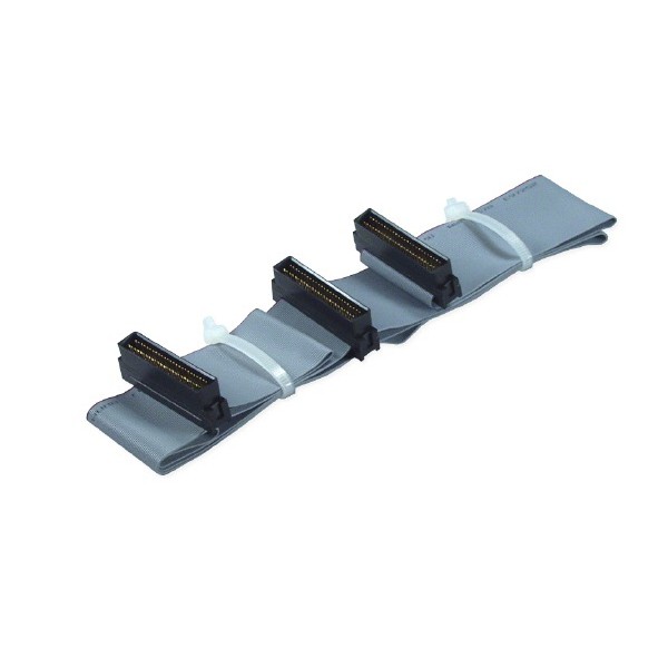
The SCSI HD 50 Dual Drives Ribbon Cable is designed to connect two hard drives to a SCSI controller. The pinout of this cable is designed to ensure that both drives can communicate properly with the controller.
Why Understanding the Pinout is Important
Understanding the pinout configuration of a 50 - pin SCSI cable is crucial for several reasons. First of all, if you're installing a SCSI device, you need to make sure that the cable is connected correctly. Incorrectly connecting the cable can lead to data transfer errors, or the device might not work at all.
Secondly, if you're troubleshooting a SCSI setup, knowing the pinout can help you identify the source of the problem. For example, if the data transfer speed is slow, you might want to check if the data lines are properly connected.
Finally, if you're designing a custom SCSI setup, understanding the pinout allows you to customize the cable to meet your specific needs. You can choose the right type of cable and make sure that all the devices are properly connected.
Contact Us for Your 50 - Pin SCSI Cable Needs
If you're in the market for high - quality 50 - Pin SCSI cables, look no further. As a trusted 50 - Pin SCSI cable supplier, we offer a wide range of 50 - pin SCSI cables to suit your needs. Whether you need a SCSI 50 Pin Cable for UltraSCSI CardBus PC Card, a Centronics 50 Pin SCSI Cable, or a SCSI HD 50 Dual Drives Ribbon Cable, we've got you covered.
We pride ourselves on providing top - notch products and excellent customer service. If you have any questions about the pinout configuration or any other aspects of our 50 - Pin SCSI cables, just reach out to us. We're here to help you make the right choice for your SCSI setup.
References
- SCSI Standards Documentation
- Technical Manuals for SCSI Devices